- 您现在的位置:买卖IC网 > Sheet目录961 > AS5304-DK-1.0 (ams)BOARD DEMO AS5304
�� ��
��
��AS5304/AS5306� Integrated� Hall� IC� for� linear� and� off-axis� rotary� motion� detection�
�7�
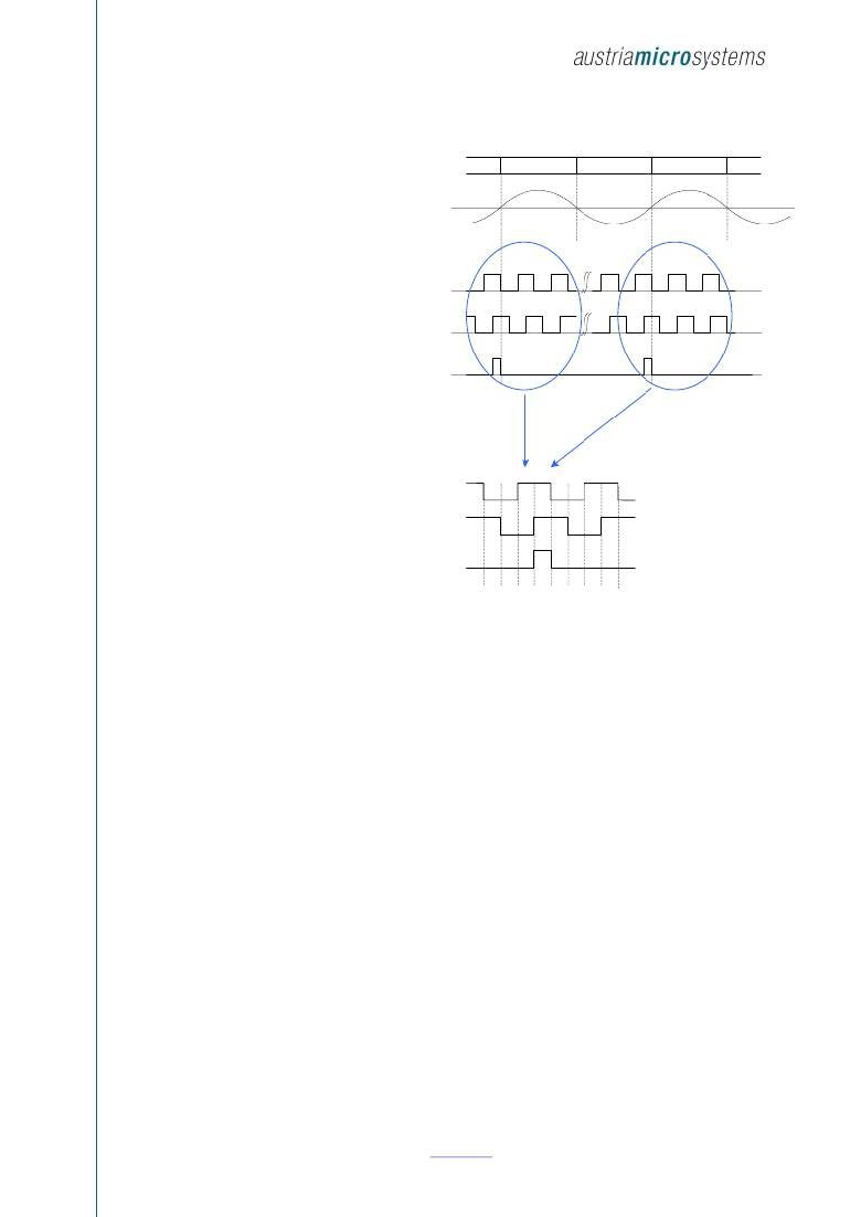
�Incremental� Quadrature� AB� Output�
�The� digital� output� is� compatible� to� optical� incremental�
�S�
�N�
�S�
�N�
�S�
�encoder� outputs.� Direction� of� rotation� is� encoded� into�
�two� signals� A� and� B� that� are� phase-shifted� by� 90o.�
�Depending� on� the� direction� of� rotation,� A� leads� B�
�(CW)� or� B� leads� A� (CCW).�
�7.1.1�
�Index� Pulse�
�A�
�40�
�1�
�2�
�40�
�1�
�2�
�A� single� index� pulse� is� generated� once� for� every� pole�
�pair.� One� pole� pair� is� interpolated� to� 40� quadrature�
�pulses� (160� steps),� so� one� index� pulse� is� generated�
�B�
�40�
�1�
�2�
�40�
�1�
�2�
��The� Index� output� is� switched� to� Index� =� high,� when� a�
�magnet� is� placed� over� the� Hall� array� as� shown� in�
��placed� over� the� left� side� of� the� IC� (top� view,� pin#1� at�
�bottom� left)� and� the� south� pole� is� placed� over� the�
�right� side� of� the� IC.�
�The� index� output� will� switch� back� to� Index� =� low,�
�when� the� magnet� is� moved� by� one� LSB� from� position�
�X=0� to� X=X1,� as� shown� in� Figure� 7,� bottom� graph.�
�One� LSB� is� 25μm� for� AS5304� and� 15μm� for� AS5306.�
�Index�
�Detail:�
�A�
�B�
�Index�
�Note:� Since� the� small� step� size� of� 1� LSB� is� hardly�
�recognizable� in� a� correctly� scaled� graph� it� is� shown� as� an�
�Step� #�
�157� 158� 159�
�0�
�1�
�2�
�3�
�4�
�5�
��Figure� 6:�
�Quadrature� A� /� B� and� Index� output�
�7.1.2�
�Magnetic� Field� Warning� Indicator�
�The� AS5304� can� also� provide� a� low� magnetic� field� warning� to� indicate� a� missing� magnet� or� when� the� end� of� the� magnetic� strip�
�has� been� reached.� This� condition� is� indicated� by� using� a� combination� of� A,� B� and� Index,� that� does� not� occur� in� normal�
�operation:�
�A� low� magnetic� field� is� indicated� with:�
�Index� =� high�
�A=B=low�
�7.1.3�
�Vertical� Distance� between� Magnet� and� IC�
�The� recommended� vertical� distance� between� magnet� and� IC� depends� on� the� strength� of� the� magnet� and� the� length� of� the�
�magnetic� pole.�
�Typically,� the� vertical� distance� between� magnet� and� chip� surface� should� not� exceed� ?� of� the� pole� length.�
�That� means� for� AS5304,� having� a� pole� length� of� 2.0mm,� the� maximum� vertical� gap� should� be� 1.0mm,�
�For� the� AS5306,� having� a� pole� length� of� 1.2mm,� the� maximum� vertical� gap� should� be� 0.6mm�
�These� figures� refer� to� the� chip� surface.� Given� a� typical� distance� of� 0.2mm� between� chip� surface� and� IC� package� surface,�
�the� recommended� vertical� distances� between� magnet� and� IC� surface� are� therefore:�
�AS� 5304:� ≤� 0.8mm�
�AS� 5306:� ≤� 0.4mm�
�Revision� 1.9�
�www.ams.com�
�Page� 6� of� 14�
�发布紧急采购,3分钟左右您将得到回复。
相关PDF资料
AS5311 DB
BOARD EVAL FOR AS5311
ASEK712ELC-05B-T-DK
BOARD EVAL FOR ASEK712ELC-05B
ASPF240D3R
RELAY SSR 3A 240VAC SIP PHASE
ASX220A06
RELAY TELECOM DPDT 10MA 6V
AT-C-26-4/4/B-10-OE-R
CORD COIL SGL END 4-4 BLACK 10'
AT-C-26-4/4/B-10/R-R
CORD COIL REVERSED 4-4 BLACK 10'
AT-C-26-4/4/B-10-R
CORD COIL STANDARD 4-4 BLACK 10'
AT-C-26-4/4/B-14-OE-R
CORD COIL SGL-END 4-4 BLACK 14'
相关代理商/技术参数
AS5304-DK-ST-1.0
制造商:ams 功能描述:Demo Board
AS5304-TS_EK_AB
功能描述:AS5304A, AS5304B - Magnetic, Linear, Rotary Position Sensor Evaluation Board 制造商:ams 系列:- 零件状态:有效 传感器类型:磁性,线性,旋转位置 感应范围:- 接口:模拟 灵敏度:- 电压 - 电源:4.5 V ~ 5.5 V 嵌入式:- 所含物品:板 使用的 IC/零件:AS5304A,AS5304B 标准包装:1
AS5304-TS_EK_DB
功能描述:AS5304/B - Hall Effect Sensor Evaluation Board 制造商:ams 系列:- 零件状态:有效 传感器类型:霍尔效应 感应范围:5mT 跳闸,60mT 释放 接口:- 灵敏度:- 电压 - 电源:9V 嵌入式:否 所含物品:2 个板,电池,夹具,磁条 使用的 IC/零件:AS5304/B 标准包装:1
AS5305
制造商:AMSCO 制造商全称:austriamicrosystems AG 功能描述:Integrated Hall IC for Linear and Off-Axis Rotary Motion Detection
AS5306/B DB
功能描述:BOARD DEMO AS5306 RoHS:否 类别:编程器,开发系统 >> 评估板 - 传感器 系列:- 产品培训模块:Lead (SnPb) Finish for COTS
Obsolescence Mitigation Program 标准包装:1 系列:-
AS5306A
制造商:AMSCO 制造商全称:austriamicrosystems AG 功能描述:Integrated Hall ICs for Linear and Off-Axis Rotary Motion Detection
AS5306A/B DB
制造商:ams 功能描述:BOARD DEMO FOR AS5306A/B
AS5306A-ATSM
功能描述:IC ENCODER 20TSSOP 制造商:ams 系列:- 零件状态:有效 编码器类型:磁性 输出类型:正交(增量) 每转脉冲数:1280 电压 - 电源:4.5 V ~ 5.5 V 致动器类型:外磁铁,不含 棘爪:无 内置开关:无 安装类型:表面贴装 朝向:- 端子类型:SMD(SMT)接片 旋转寿命(最少次数):- 标准包装:500